Cranks and cams
by Chris Woodford. Last updated: September 22, 2022.
What sort of problems keep you awake at night? If you'd been an engineer during the Industrial Revolution, tinkering with steam engines and such, cams and cranks were the kind of thing you'd have worried about. They're cunning inventions that convert the push-pull motion of engines and machines into the spinning and whirring motion of wheels—or vice-versa. Cranks and cams are just as useful today and you can find them in everything from car engines and bicycle pedals to electric toothbrushes and sewing machines. Here's a quick look at how they work!
Photo: This radio doesn't need batteries because it's powered by a simple hand-crank: when you crank the handle, you spin a small electricity generator (dynamo) inside the case that stores energy in rechargeable batteries. Although you're turning the crank, if you do it for a while you soon get a distinct feeling that you're moving your hand back and forth instead of round-and-round. So the crank is really converting a back-and-forth motion of your hand into rotary motion in the generator. Photo by Robert J. Fluegel courtesy of US Navy and Wikimedia Commons.
Sponsored links
Contents
How do cranks work?
Engines that make their power with pistons usually need a way of converting back-and-forth (reciprocating) motion into round-and-round (rotational) motion—a way of driving a wheel, in other words. Most engines use cranks to do this. A crank is simply an off-center connection that provides energy to (or takes energy from) a rotating wheel. As the crank pushes back and forth, the wheel rotates (or vice-versa). In this example, as the red wheel rotates, the green crank pushes the black and blue connecting rods back and forth, converting the wheel's rotary motion into reciprocal motion. So the red wheel moves round, but the blue rod moves back and forth.

The same mechanism could be used the opposite way to drive the wheel from a piston. You'd just hitch the blue rod up to the piston so that as it moved in and out of its cylinder, the red wheel would go round and round. Steam engine wheels are driven exactly like this.
How do cams work?
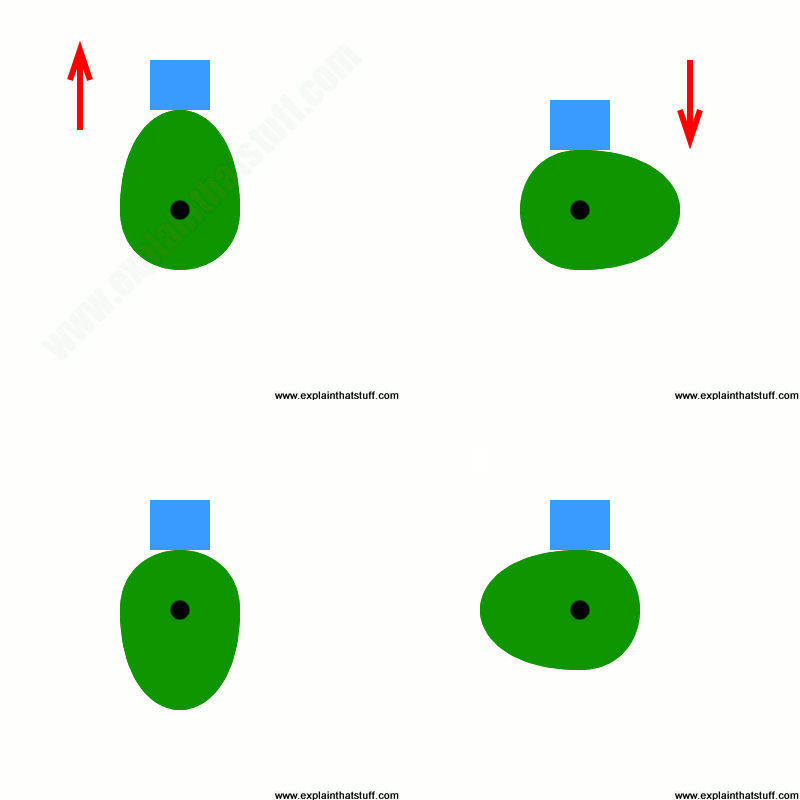
Cams generally do the opposite job to cranks: they turn rotary motion into reciprocating motion. Whatever you need to move up and down (or back and forth) rests on top of an oval wheel, sometimes mounted off-center (the cam). As the cam rotates, the object it supports rises up and down. In this example, you can see the blue box rises and falls as the green cam turns round and round. But most of the time the box just sits there, motionless, with the cam slowly spinning beneath it. If you look closely at the way I've drawn the cam, you can see the secret of how it works. Three "quarters" of it is like a circle, so anything resting on it for three quarters of the time will neither rise nor fall, but stay motionless. The other quarter stretches out into an ellipse shape and that's the part that lifts and lowers every time it reaches the top.

The object that moves up and down, or otherwise tracks the cam's movement, is called (surprise, surprise) the follower. It could be a simple rod or lever (as I've shown here), a pointer, a rotating roller, or something more intricate and complex.
The cam, too, can vary in design. A classic cam is oval (pear-shaped) like the one I've drawn here, but others are heart-shaped, hexagonal, round but eccentric (a circle that rotates about an off-centered point), elliptical (a more symmetrical oval than our pear-shaped cam), snail-shaped (a circle with a tail), or pretty much anything else you can think of. Where the shape of the cam controls the path that the follower traces, both its size and shape control the timing of its motion. So, for example, if I stretched my green oval taller, the blue box would not only move higher but take longer to return to position. That can be handy if cams are being used for things like opening and closing valves on engines (see the illustration further down this page under the examples of cams).

Artwork: Cam shapes: Here are eight typical designs, but you can make cams any shape and size you need to (even a completely irregular shape). The cam turns around the blue circle in each case.
Examples of cranks
It's all very well to talk about things in theory with little animated graphics, but it's much more interesting to see how these things work in actual machines. The following selection of photos shows you some examples of cranks working hard in real life.
Engine crankshaft
Car and boat engines have multiple cylinders that turn a single drive shaft, called the crankshaft. Each cylinder fires at a slightly different time so, at any given moment, there's always at least one cylinder adding power and driving the vehicle along. The cylinders are attached to the crankshaft by rods that connect to the piston rods inside the cylinders.

Photo: The shiny crankshaft from a brand new marine engine. Picture by Marco Bernardini published on Flickr in 2009 under a Creative Commons Licence.
Steam engine crankshaft

Photo: A fairly small beam engine in the engine hall at Think Tank, the science and engineering museum in Birmingham, England. You can just about see the cylinder and piston on the left, the rocking beam on top, and the crankshaft and connecting rod driving the wheel on the right.
Early steam engines were so big that they were permanently fixed in place, often occupying entire huge buildings. An engine like this typically makes power with a single piston moving in and out of a single cylinder. If you need it drive a wheel, you can attach the piston to a beam. As the piston moves up and down, the beam rocks back and forth, pulling on a crankshaft and connecting rod that turn the wheel.
Hand-cranked pump

Photo: Hand-cranked rotary pump. Picture by Ian Schell courtesy of US Army.
Hand cranks are great ways to drive machines with the help of muscle power! Our top photo shows a hand crank being used to generate electricity. Here we have a hand crank turning a rotary pump that's being used to transport fuel down a pipeline. The crank is turning an impeller (a kind of turbine-like device) sealed inside the red casing, which powers the fluid along.
Bicycle pedals

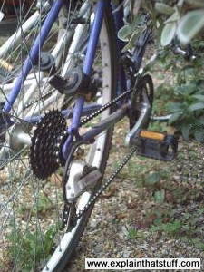
Photo: Bicycle pedals would be better referred to as "bicycle cranks," because it's the cranks attached to the pedals that do the work!
Here's one of the most familiar cranks of them all! We always talk about the "pedals" on a bicycle when we really mean the cranks—two levers that help to multiply the force supplied by our leg muscles as they pump up and down. In theory, the longer the cranks, the better—because that gives more leverage. In practice, though, the cranks have to be short enough for your legs to operate the pedals comfortably and not so long that they bang on the ground. The cranks combine with the gears to make the bicycle just about the most efficient form of transportation so far invented.
Electric shavers
Electric shavers (and similar, powered chopping machines like garden hedge trimmers and electric carving knives) cut using two parallel sets of toothed blades: one stays static while the other slides past it from side to side. How does that work? An electric motor inside the case turns a wheel with an off-center peg attached, which works like a crank. The peg engages a slot in a piece of plastic attached to the lower set of blades. As the motor spins, the peg moves from side to side (and also up and down), pushing the slot from side to side in turn, causing the moving blades to slide back and forth against the static blades. Now this doesn't look like a crank at first sight, but if you think about the peg and the plastic slot, you can see that they work in the same way as the other crank mechanisms we explored up above.

Photo: Inside a shaver: A crank-like mechanism (a peg that engages in a slot) moves one of the cutting blades back and forth. The top photo shows a typical electric shaver as you look down on it; the bottom photos show you what you see when you pull the blades away for cleaning. The left photo shows the mechanism inside the shaver; the right photo shows the underside of the blades.
Lawn sprinklers
How does a lawn sprinkler oscillate back and forth using only the power of water? Look closely at a sprinkler and you'll see a little crank (gray in the picture below) that rotates (white arrow) as the water pushes through the pipe. As the crank turns, it pulls the silver bar (through which the spray emerges) back and forth, shooting the water out at different angles (blue arrows). For more technical details of the mechanism, take a look at Sunbeam's 1956 patent US2914255A: Lawn Sprinkler and the 1968 British patent GB1176978A: Improvements in or relating to Oscillating Means, for example for Lawn Sprinklers (which describes the Hozelock sprinkler you can see below).

Photo: How a garden lawn sprinkler works. As the crank (gray) rotates, water sprays out at different angles (blue).
Sponsored links
Examples of cams
From door locks and prosthetic legs to old-fashioned (gear-driven) calculators and photocopiers, cams are working their magic inside all kinds of machines, turning rotation into back and forth motion. It's almost impossible to find good pictures of working cams, but I'm constantly looking out for examples; I'll post more here as I discover them.
Engine valves
Car engines burn fuel with air to release energy that roars us down the road. A typical car has 4–8 cylinders in which the power is made. They suck in fuel and air one minute, burn it to make power, and blast out exhaust gases the next. Little valves mounted on each cylinder allow fuel in and let the waste gases escape. The cylinders make power slightly out of step with one another, and their valves have to be opened and closed with meticulous timing by cams attached to a spinning axle called a camshaft.

Artwork: How a cam opens and closes the valves in a car engine. The cam (red) is rotated by a camshaft (gray) powered by a belt linked to the crankshaft (not shown). As it turns, the cam pushes a rod called a tappet (blue) back and forth. The tappet moves a rocker arm (green) which allows a poppet valve (orange) to move in and out against the pressure of a spring (purple). So the rotating cam makes the valve reciprocate (open and close). Artwork from US Patent 3,302,628: Internal combustion engine valve gear by Clayton Blaine Leach, General Motors Corporation, February 7, 1967, courtesy of US Patent and Trademark Office.
Stamping machine
Snail cams (sometimes called drop cams) are perfect for slowly lifting heavy machine parts that drop back down very quickly, hammering or stamping something in the process. With the green egg-shaped cam I've illustrated in my animation up above, the movement is perfectly symmetrical: the blue follower rises at exactly the same speed as it falls. With a snail cam, however, the rising happens slowly and gently, while the falling is quick and hard. You can see from this example why cams are sometimes very oddly shaped: although they follow a continually repeated cycle, some parts of the cycle might need to happen more quickly or abruptly than others.

Photo: A camshaft on an old stamping machine in a gold mill. As the shaft turns, the heavy weights slowly rise up and then suddenly drop down very hard. Picture by Jet Lowe, taken at Lost Horse Gold Mine, courtesy of US Library of Congress.
Hammers operated by cams were one of many ingenious mechanisms invented by Leonardo da Vinci. [1]
Door locks, bolts, and hinges
When you turn your key, you make a bolt shift from side to side that either locks or unlocks your door. What converts the rotation of your key into a sliding motion of the bolt? Often it's a cam of some sort. Different locks and bolts work in many different—often mechanically intricate—ways (see our article on door locks for more details); here's one very simple example of how a cam can power a locking door hinge.

Artwork: The cam in a spring-loaded door hinge. Doors on closets need to stay closed—and this is one way to achieve that with what is effectively a spring-loaded cam follower. When the hinged door (blue) is open and pointing to the right, a notch in the cam follower (red) and a spring (yellow) hold it securely in place. When you close the door, you rotate the cam (clockwise), which moves the follower and pushes the spring in briefly, before it pops back out again and locks the cam (and the door) in the opposite, closed position. Artwork from US Patent 324,444: Lock hinge by J Wolf, August 18, 1885, courtesy of US Patent and Trademark Office.
Seed-planting machine
This model of a popular seed-drilling machine from the 1930s shows how a star-shaped cam can be put to practical use. The cam (red) rotates as the front wheel travels over the ground. The blue lever (the follower) rises up and down in step and the "planting shoe" on the bottom sets the seeds at variable depths, as shown by the wavy yellow path.

Photo: A star-shaped cam used in a model of a seed drill developed by John Randolph, an engineer of the U.S. Bureau of Agriculture Engineering, in the 1930s. Photo by Harris & Ewing courtesy of US Library of Congress. More details of how it works in US Patent 1,892,250.
Force or speed?
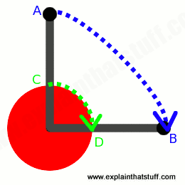
Cranks are closely related to levers and gears: all three of these can be used to magnify force or speed, although not both at the same time. Suppose you're turning the handle of the clockwork radio in our top picture. Your hand goes round in a larger circle than the mechanism in the center, so it's traveling faster. A crank used in this way reduces speed and increases force. Most cranks work like this, providing leverage to give extra force. A coffee grinder is another good example: it takes quite a lot of force to power the crushers (burrs) that smash the beans to pieces and the handle of the grinder multiplies the force you apply with your hands. If you use a crank the opposite way, using the power from a cylinder and piston to drive a rotating wheel, you can use it to increase the speed of a machine, although the force you get will be reduced at the same time.

Artwork: How a crank works: If you turn the outside of the crank through a quarter circle, it moves a distance from point A to point B. The inside of the crank moves a much shorter distance from point C to point D. Since the distance AB is much bigger than the distance CD, and both these distances are covered in the same time, it's clear the outside of the crank is moving faster than the inside, so the crank reduces speed at the center. What's less obvious is that the crank increases force in exactly the same proportion. So if it gives a ten-fold reduction in speed, it also gives a ten-fold increase in force.
Why can't you increase the speed and the force simultaneously? Because of a basic law of physics called the conservation of energy. Suppose you're cranking the clockwork radio. You apply a certain force to the handle to move it a certain distance in one second. That takes a certain amount of energy, which your body supplies. Now the law of conservation of energy tells us nothing can magically create energy out of thin air: the energy you supply to the outside (the crank handle) must be the same (or a bit less) than the energy received at the inside (the center of the crank where the clockwork mechanism is located). We know we're getting more force at the center of the crank than at the outside; we also know that the inside of the crank turns more slowly (less distance each second) than the outside. So the greater force is compensated by that force moving a shorter distance each second. Every second, the energy supplied to the inner, clockwork mechanism at the center (the larger force times the shorter distance) is virtually the same as the energy we put in at the outer part of the crank (the smaller force times the longer distance).
About the author
Chris Woodford is the author and editor of dozens of science and technology books for adults and children, including DK's worldwide bestselling Cool Stuff series and Atoms Under the Floorboards, which won the American Institute of Physics Science Writing award in 2016. You can hire him to write books, articles, scripts, corporate copy, and more via his website chriswoodford.com.
