Flick a switch and get instant power—how our ancestors would have loved
electric motors! You can find them in everything from
electric trains to remote-controlled
cars—and you might be surprised how common they are. How many electric
motors are there in the room with you right now? There are probably two
in your computer for starters, one spinning your hard
drive around and another one powering the cooling fan. If
you're sitting in a bedroom, you'll find motors in hair dryers and many
toys; in the bathroom, they're in extractor fans, and electric shavers;
in the kitchen, motors are in just about every appliance from clothes washing machines and dishwashers to coffee grinders, microwaves, and electric can openers.
Electric motors have proved themselves to be among the greatest
inventions of all time. Let's pull some apart and find out how they
work!
Photo: Even small electric motors are surprisingly heavy.
That's because they're packed with tightly wound copper and heavy magnets.
This is the motor from an old electric lawn mower. The copper-colored thing toward the
front of the axle, with slits cut into it, is the commutator that keeps the motor
spinning in the same direction (as explained below).
The basic idea of an electric motor is really simple: you put electricity into it at one end and an
axle
(metal rod) rotates at the other end giving you the power to drive a
machine of some kind. How does this work in practice? Exactly how do
your
convert electricity into movement? To find the answer to that, we have
to go back in time almost 200 years.
Suppose you take a length of ordinary wire, make it into a big loop,
and lay it between the poles of a powerful, permanent horseshoe
magnet.
Now if you connect the two ends of the wire to a battery,
the wire will jump
up briefly. It's amazing when you see this for the first time. It's
just like magic! But there's a perfectly scientific
explanation. When an
electric current starts to creep along a wire, it creates a
magnetic field all around it. If you place the wire near a permanent
magnet, this temporary magnetic field interacts with the permanent
magnet's field. You'll know that two magnets placed near one another
either attract or repel. In the same way, the temporary magnetism
around the wire attracts or repels the permanent magnetism from the
magnet, and that's what causes the wire to jump.
Fleming's Left-Hand Rule
You can figure out the direction in which the wire will jump using a
handy mnemonic (memory aid) called Fleming's Left-Hand Rule (sometimes
called the Motor Rule).
Hold out the thumb, first finger, and second finger of your left
hand so all three are at right angles. If you point the seCond finger
in the direction of the Current
(which flows from the positive to the
negative terminal of the battery), and the First
finger in the
direction of the Field (which
flows from the North to the South pole of
the magnet), your thuMb will
show the direction in which the wire
Moves.
That's...
First finger = Field
SeCond finger = Current
ThuMb = Motion
A quick word about current
If you're confused by me saying that the current flows from positive to negative,
that just happens to be a historical convention. People like Benjamin Franklin, who helped figure out
the mystery of electricity back in the 18th century, believed it was a flow of positive charges,
so it flowed from positive to negative. We call this idea conventional current
and still use it to this day in things like Fleming's Left-Hand Rule. Now we have better ideas about how
electricity works, we tend to talk about current as a flow of electrons, from negative to positive, in the opposite direction to the conventional current. When you're trying to figure out the rotation of a motor or a generator,
be sure to remember that current means conventional current and not electron flow.
Sponsored links
How an electric motor works—in theory
The link between electricity, magnetism, and movement was originally
discovered in 1820 by French physicist André-Marie
Ampère
(1775–1867) and it's the basic science behind an electric motor. But if
we want to turn this amazing scientific discovery into a more practical
bit of technology to power our electric mowers and toothbrushes, we've got to take it a little bit further. The inventors who did that were Englishmen Michael Faraday (1791–1867)
and William Sturgeon (1783–1850) and American
Joseph Henry (1797–1878). Here's how they
arrived at their brilliant invention.
Suppose we bend our wire into a squarish, U-shaped loop so there are
effectively
two parallel wires running through the magnetic field. One of them
takes the electric current away from us through the wire and the other
one brings the current back again. Because the current flows in
opposite directions in the wires, Fleming's Left-Hand Rule tells us the
two wires will move in opposite directions. In other words, when we
switch on the electricity, one of the wires will move upward and the
other will move downward.
Photo: My model electric motor has a loop of wire (center) connected to
red and black power leads. The current flows counter-clockwise. The loop sits in between the poles of a magnet (N/S), so the field flows from left to right. In this arrangement, Fleming's Left-Hand Rule shows us
that the left side of the loop moves upward and the right side moves downward.
If the coil of wire could carry on moving like this, it would rotate
continuously—and we'd be well on the way to making an electric
motor. But that can't happen with our present setup: the wires will
quickly tangle up. Not only that, but if the coil could rotate far
enough, something else would happen. Once the coil reached the vertical
position, it would flip over, so the electric current would effectively
be flowing through it the opposite way.
Photo: When the loop reached the vertical position, the power leads would need to cross over. The red lead would now be on the left and the black lead on the right.
If the loop had enough momentum to swing past the vertical, the current would effectively reverse.
It would still flow from red and toward black, but it would now flow round the loop clockwise.
Photo: If the loop managed to flip over, the power leads would cross over completely. The red lead would now be on the left and the black on the right, so the current would now flow around the loop clockwise.
Now the forces on each side of the coil would reverse. Fleming's Left-Hand Rule tells us there would be a downward force on the left side of the coil and an upward force on the right side.
Instead of rotating continuously in the same direction, it would move back in the direction it had just come!
Imagine an electric train with a motor like this: it would keep
shuffling back and forward on the spot without ever actually going
anywhere.
How an electric motor works—in practice
There are two ways to overcome this problem. One is to use a kind of
electric current that periodically reverses direction, which is known
as an alternating current (AC).
In the kind of small, battery-powered
motors we use around the home, a better solution is to add a component
called a commutator to the
ends of the coil. (Don't worry about the meaningless technical
name: this slightly old-fashioned word "commutation" is a bit like the
word "commute". It simply means to change back and forth in the same
way that commute means to travel back and forth.) In its simplest form, the
commutator is a metal ring divided into two separate halves and
its job is to reverse the electric current in the coil each time the
coil rotates through half a turn. One end of the coil is attached to
each half of the commutator. The electric current from the battery
connects to the motor's electric terminals.
These feed electric power into the commutator through a pair of loose
connectors called brushes,
made
either from pieces of graphite (soft carbon similar to pencil
"lead") or thin lengths of springy metal,
which (as
the name suggests) "brush" against the commutator. With the
commutator in place, when electricity flows through the circuit, the
coil will rotate continually in the same direction.
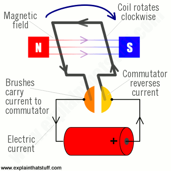
Artwork: A simplified diagram of the parts in an electric
motor. Animation: How it works in practice. Note how the commutator reverses the current each time the coil turns
halfway. This means the force on each side of the coil is always
pushing in the same direction, which keeps the coil rotating clockwise.
A simple, experimental motor such as this isn't capable of making
much power. We can increase the turning force (or torque)
that the
motor can create in three ways: either we can have a more
powerful permanent magnet, or we can increase the electric current
flowing through the wire, or we can make the coil so it has many
"turns" (loops) of very thin wire instead of one "turn" of thick wire.
In practice, a motor also has the permanent magnet curved in a
circular shape so it almost touches the coil of wire that rotates
inside it. The closer together the magnet and the coil, the
greater the force the motor can produce.
Although we've described a number of different parts, you can think of a motor as having just two essential components:
There's a permanent magnet (or magnets) around the edge of the motor case that remains static, so it's called the stator of a motor.
Inside the stator, there's the coil, mounted on an axle that spins around at high speed—and this is called the rotor. The rotor also includes the commutator.
Photo: An electrician repairs an electric motor
onboard an aircraft carrier.
The shiny metal he's using may look like gold,
but it's actually copper,
a good conductor that is much less expensive. Photo by Jason Jacobowitz courtesy of US Navy and
Wikimedia Commons.
Universal motors
DC motors like this are great for battery-powered toys (things like model trains, radio-controlled cars, or electric shavers), but you don't find them in many household appliances. Small appliances (things like coffee grinders or electric food blenders) tend to use what are called universal motors, which can be powered by either AC or DC. Unlike a simple DC motor, a universal motor has an electromagnet, instead of a permanent magnet, and it takes its power from the DC or AC power you feed in:
When you feed in DC, the electromagnet works like a conventional permanent magnet and produces a magnetic field that's always pointing in the same direction. The commutator reverses the coil current every time the coil flips over, just like in a simple DC motor, so the coil always spins in the same direction.
When you feed in AC, however, the current flowing through the electromagnet and the current flowing through the coil both reverse, exactly in step, so the force on the coil is always in the same direction and the motor always spins either clockwise or counter-clockwise. What about the commutator? The frequency of the current changes much faster than the motor rotates and, because the field and the current are always in step, it doesn't actually matter what position the commutator is in at any given moment.
Animation: How a universal motor works: The electricity supply powers both the magnetic field and the rotating coil. With a DC supply, a universal motor works just like a conventional DC one, as above. With an AC supply, both the magnetic field and coil current change direction every time the supply current reverses. That means the force on the coil is always pointing the same way.
Photo: Inside a typical universal motor: The main parts inside a medium-sized motor from a coffee grinder, which can run on either DC or AC. The gray electromagnet round the edge is the stator (static part) and its powered by the orange-colored coils. Note also the slits in the commutator and the carbon brushes pushing against it, which provide power to the rotor (rotating part). Induction motors in such things as electric railroad trains are many times bigger and more powerful than this, and always work using high-voltage alternating current (AC), instead of low-voltage direct current (DC), or the moderately low voltage household AC that powers universal motors.
In simple DC and universal motors, the rotor spins inside the stator. The rotor is a coil connected to the electric power supply and the stator is a permanent magnet or electromagnet. Large AC motors (used in things like factory machines) work in a slightly different way: they pass alternating current through opposing pairs of magnets to create a rotating magnetic field, which "induces" (creates) a magnetic field in the motor's rotor, causing it to spin around. You can read more about this in our article on AC induction motors. If you take one of these induction motors and "unwrap" it, so the stator is effectively laid out into a long continuous track, the rotor can roll along it in a straight line. This ingenious design is known as a linear motor, and you'll find it in such things as factory machines and floating "maglev" (magnetic levitation) railroads.
Another interesting design is the brushless DC (BLDC) motor. The stator and rotor effectively swap over, with multiple iron coils static at the center and the permanent magnet rotating around them, and the commutator and brushes are replaced by an electronic circuit. You can read more in our main article on hub motors.
Stepper motors, which turn around through precisely controlled angles, are a variation of brushless DC motors.
How to Print an Electric Motor by Carl Bugeja. IEEE Spectrum, August 24, 2018. Can you "print" a motor in a similar way to how you make a printed circuit board?
Power and Electric Motors by Rhett Allain. Wired, November, 2011. Why do electric motors draw much more power when they're just starting up?
Activities
Here are some safe and simple motor-making activities you can try for yourself. In order of difficulty, the first is a simple screw motor; the last is a fully-fledged DC commutator motor.
How to make the simplest electric motor by Windell Oskay. Evil Mad Scientist, August 7, 2006. Can you really make a motor from a battery, a screw, a magnet, and a strip of wire?
Very simple screw 'motor' by Dr Jonathan Hare, Creative Science Centre. Another description of a screw motor.
Patents are a great source of detailed technical information and drawings. Here are a few I've dug out from the USPTO database:
Electric Motor by Hans E. Nietsche, April 13, 1925. A typical early DC motor designed to be powered by low-voltage batteries.
DC Electric Motor by Masayuki Yokoyama et al, Mitsubishi Electric Corporation, June 1, 2010. A longer-life motor with an improved design of commutator.
Please do NOT copy our articles onto blogs and other websites
Articles from this website are registered at the US Copyright Office. Copying or otherwise using registered works without permission, removing this or other copyright notices, and/or infringing related rights could make you liable to severe civil or criminal penalties.